CoderFunda
  • Home
  • About us
    • Contact Us
    • Disclaimer
    • Privacy Policy
    • About us
  • Home
  • Php
  • HTML
  • CSS
  • JavaScript
    • JavaScript
    • Jquery
    • JqueryUI
    • Stock
  • SQL
  • Vue.Js
  • Python
  • Wordpress
  • C++
    • C++
    • C
  • Laravel
    • Laravel
      • Overview
      • Namespaces
      • Middleware
      • Routing
      • Configuration
      • Application Structure
      • Installation
    • Overview
  • DBMS
    • DBMS
      • PL/SQL
      • SQLite
      • MongoDB
      • Cassandra
      • MySQL
      • Oracle
      • CouchDB
      • Neo4j
      • DB2
      • Quiz
    • Overview
  • Entertainment
    • TV Series Update
    • Movie Review
    • Movie Review
  • More
    • Vue. Js
    • Php Question
    • Php Interview Question
    • Laravel Interview Question
    • SQL Interview Question
    • IAS Interview Question
    • PCS Interview Question
    • Technology
    • Other

04 April, 2022

Relational Model concept

 Programing Coderfunda     April 04, 2022     DBMS     No comments   


Relational Model concept

The relational model can represent as a table with columns and rows. Each row is known as a tuple. Each table of the column has a name or attribute.

Domain: It contains a set of atomic values that an attribute can take.

Attribute: It contains the name of a column in a particular table. Each attribute Ai must have a domain, dom(Ai)

Relational instance: In the relational database system, the relational instance is represented by a finite set of tuples. Relation instances do not have duplicate tuples.

Relational schema: A relational schema contains the name of the relation and the name of all columns or attributes.

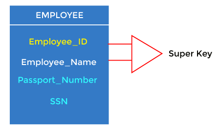
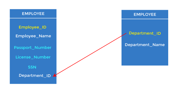
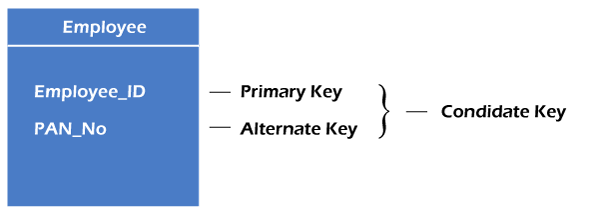
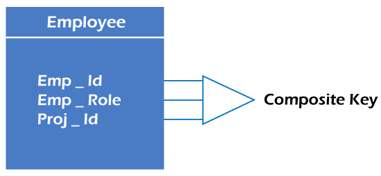
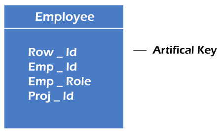
Relational key: In the relational key, each row has one or more attributes. It can identify the row in the relation uniquely.

Example: STUDENT Relation

NAMEROLL_NOPHONE_NOADDRESSAGE
Ram147957305758992Noida24
Shyam128399026288936Delhi35
Laxman332898583287182Gurugram20
Mahesh278577086819134Ghaziabad27
Ganesh172829028 9i3988Delhi40
  • In the given table, NAME, ROLL_NO, PHONE_NO, ADDRESS, and AGE are the attributes.
  • The instance of schema STUDENT has 5 tuples.
  • t3 = <Laxman, 33289, 8583287182, Gurugram, 20>

Properties of Relations

  • The name of the relation is distinct from all other relations.
  • Each relation cell contains exactly one atomic (single) value
  • Each attribute contains a distinct name
  • The attribute domain has no significance
  • tuple has no duplicate value
  • The order of tuple can have a different sequence
Read More
  • Share This:  
  •  Facebook
  •  Twitter
  •  Google+
  •  Stumble
  •  Digg

Relationship of higher degree

 Programing Coderfunda     April 04, 2022     DBMS     No comments   

Relationship of higher degree

The degree of relationship can be defined as the number of occurrences in one entity that is associated with the number of occurrences in another entity.

There are the three degrees of relationship:

  1. One-to-one (1:1)
  2. One-to-many (1:M)
  3. Many-to-many (M: N)

1. One-to-one

  • In a one-to-one relationship, one occurrence of an entity relates to only one occurrence in another entity.
  • A one-to-one relationship rarely exists in practice.
  • For example: if an employee is allocated a company car then that car can only be driven by that employee.
  • Therefore, employees and company cars have a one-to-one relationship.

DBMS Relationship of higher degree

2. One-to-many

  • In a one-to-many relationship, one occurrence in an entity relates to many occurrences in another entity.
  • For example, An employee works in one department, but a department has many employees.
  • Therefore, department and employee have a one-to-many relationship.

DBMS Relationship of higher degree

3. Many-to-many

  • In a many-to-many relationship, many occurrences in an entity relate to many occurrences in another entity.
  • Same like a one-to-one relationship, the many-to-many relationship rarely exists in practice.
  • For example: At the same time, an employee can work on several projects, and a project has a team of many employees.
  • Therefore, employee and project have a many-to-many relationship.

DBMS Relationship of higher degree
Read More
  • Share This:  
  •  Facebook
  •  Twitter
  •  Google+
  •  Stumble
  •  Digg

Reduction of ER diagram to Table

 Programing Coderfunda     April 04, 2022     DBMS     No comments   

Reduction of ER diagram to Table

The database can be represented using the notations, and these notations can be reduced to a collection of tables.

In the database, every entity set or relationship set can be represented in tabular form.

The ER diagram is given below:


DBMS Reduction of ER diagram to Table

There are some points for converting the ER diagram to the table:

  • Entity type becomes a table.

In the given ER diagram, LECTURE, STUDENT, SUBJECT and COURSE forms individual tables.

  • All single-valued attribute becomes a column for the table.

In the STUDENT entity, STUDENT_NAME and STUDENT_ID form the column of STUDENT table. Similarly, COURSE_NAME and COURSE_ID form the column of COURSE table and so on.

  • A key attribute of the entity type represented by the primary key.

In the given ER diagram, COURSE_ID, STUDENT_ID, SUBJECT_ID, and LECTURE_ID are the key attribute of the entity.

  • The multivalued attribute is represented by a separate table.

In the student table, a hobby is a multivalued attribute. So it is not possible to represent multiple values in a single column of STUDENT table. Hence we create a table STUD_HOBBY with column name STUDENT_ID and HOBBY. Using both the column, we create a composite key.

  • Composite attribute represented by components.

In the given ER diagram, student address is a composite attribute. It contains CITY, PIN, DOOR#, STREET, and STATE. In the STUDENT table, these attributes can merge as an individual column.

  • Derived attributes are not considered in the table.

In the STUDENT table, Age is the derived attribute. It can be calculated at any point of time by calculating the difference between current date and Date of Birth.

Using these rules, you can convert the ER diagram to tables and columns and assign the mapping between the tables. Table structure for the given ER diagram is as below:


DBMS Reduction of ER diagram to Table

Figure: Table structure

Read More
  • Share This:  
  •  Facebook
  •  Twitter
  •  Google+
  •  Stumble
  •  Digg

Aggregation

 Programing Coderfunda     April 04, 2022     No comments   

Aggregation

In aggregation, the relation between two entities is treated as a single entity. In aggregation, the higher-level relationship with its corresponding entities is aggregated into a higher-level entity.

For example, the Center entity offers the Course entity to act as a single entity in the relationship which is in relationship with another entity visitor. In the real world, if a visitor visits a coaching center then he will never inquire about the Course only or just about the Center instead he will ask inquiry about both.


DBMS Aggregation

Read More
  • Share This:  
  •  Facebook
  •  Twitter
  •  Google+
  •  Stumble
  •  Digg

Specialization

 Programing Coderfunda     April 04, 2022     DBMS     No comments   


Specialization

  • Specialization is a top-down approach, and it is opposite to Generalization. In specialization, one higher level entity can be broken down into two lower level entities.
  • Specialization is used to identify the subset of an entity set that shares some distinguishing characteristics.
  • Normally, the superclass is defined first, the subclass and its related attributes are defined next, and relationship set are then added.

For example: In an Employee management system, EMPLOYEE entity can be specialized as TESTER or DEVELOPER based on what role they play in the company.


DBMS Specialization
Read More
  • Share This:  
  •  Facebook
  •  Twitter
  •  Google+
  •  Stumble
  •  Digg

Generalization

 Programing Coderfunda     April 04, 2022     DBMS     No comments   

Generalization

  • Generalization is like a bottom-up approach in which two or more entities of lower-level levels combine to form a higher-level entity if they have some attributes in common.
  • In generalization, an entity of a higher level can also combine with the lower level entities to form a further higher-level entity.
  • Generalization is more like a subclass and superclass system, but the only difference is the approach. Generalization uses the bottom-up approach.
  • In generalization, entities are combined to form a more generalized entity, i.e., subclasses are combined to make a superclass.

For example, Faculty and Student entities can be generalized and create a higher level entity Person.


DBMS Generalization

Read More
  • Share This:  
  •  Facebook
  •  Twitter
  •  Google+
  •  Stumble
  •  Digg

DBMS Keys

 Programing Coderfunda     April 04, 2022     DBMS     No comments   

Keys

  • Keys play an important role in the relational database.
  • It is used to uniquely identify any record or row of data from the table. It is also used to establish and identify relationships between tables.

For example, ID is used as a key in the Student table because it is unique for each student. In the PERSON table, passport_number, license_number, and SSNand are keys since they are unique for each person.

DBMS Keys

Types of keys:

DBMS Keys

1. Primary key

  • It is the first key used to identify one and only one instance of an entity uniquely. An entity can contain multiple keys, as we saw in the PERSON table. The key which is most suitable from those lists becomes the primary key.
  • In the EMPLOYEE table, ID can be the primary key since it is unique for each employee. In the EMPLOYEE table, we can even select License_Number and Passport_Number as primary keys since they are also unique.
  • For each entity, the primary key selection is based on requirements and developers.
DBMS Keys

2. Candidate key

  • A candidate key is an attribute or set of attributes that can uniquely identify a tuple.
  • Except for the primary key, the remaining attributes are considered candidate keys. The candidate keys are as strong as the primary key.

For example: In the EMPLOYEE table, id is best suited for the primary key. The rest of the attributes, like SSN, Passport_Number, License_Number, etc., are considered candidate keys.

DBMS Keys

3. Super Key

A super key is an attribute set that can uniquely identify a tuple. A super key is a superset of a candidate key.

DBMS Keys

For example: In the above EMPLOYEE table, for(EMPLOEE_ID, EMPLOYEE_NAME), the name of two employees can be the same, but their EMPLYEE_ID can't be the same. Hence, this combination can also be a key.

The super key would be EMPLOYEE-ID (EMPLOYEE_ID, EMPLOYEE-NAME), etc.

4. Foreign key

  • Foreign keys are the column of the table used to point to the primary key of another table.
  • Every employee works in a specific department in a company, and employee and department are two different entities. So we can't store the department's information on the employee table. That's why we link these two tables through the primary key of one table.
  • We add the primary key of the DEPARTMENT table, Department_Id, as a new attribute in the EMPLOYEE table.
  • In the EMPLOYEE table, Department_Id is the foreign key, and both the tables are related.
DBMS Keys

5. Alternate key

There may be one or more attributes or a combination of attributes that uniquely identify each tuple in a relation. These attributes or combinations of the attributes are called the candidate keys. One key is chosen as the primary key from these candidate keys, and the remaining candidate key, if it exists, is termed the alternate key. In other words, the total number of alternate keys is the total number of candidate keys minus the primary key. The alternate key may or may not exist. If there is only one candidate key in a relation, it does not have an alternate key.

For example, employee relation has two attributes, Employee_Id and PAN_No, that act as candidate keys. In this relation, Employee_Id is chosen as the primary key, so the other candidate key, PAN_No, acts as the Alternate key.

DBMS Keys

6. Composite key

Whenever a primary key consists of more than one attribute, it is known as a composite key. This key is also known as Concatenated Key.

DBMS Keys

For example, in employee relations, we assume that an employee may be assigned multiple roles, and an employee may work on multiple projects simultaneously. So the primary key will be composed of all three attributes, namely Emp_ID, Emp_role, and Proj_ID in combination. So these attributes act as a composite key since the primary key comprises more than one attribute.

DBMS Keys

7. Artificial key

The key created using arbitrarily assigned data are known as artificial keys. These keys are created when a primary key is large and complex and has no relationship with many other relations. The data values of the artificial keys are usually numbered in a serial order.

For example, the primary key, which is composed of Emp_ID, Emp_role, and Proj_ID, is large in employee relations. So it would be better to add a new virtual attribute to identify each tuple in the relation uniquely.

Read More
  • Share This:  
  •  Facebook
  •  Twitter
  •  Google+
  •  Stumble
  •  Digg

Mapping Constraints

 Programing Coderfunda     April 04, 2022     DBMS     No comments   


Mapping Constraints

  • A mapping constraint is a data constraint that expresses the number of entities to which another entity can be related via a relationship set.
  • It is most useful in describing the relationship sets that involve more than two entity sets.
  • For binary relationship set R on an entity set A and B, there are four possible mapping cardinalities. These are as follows:
    1. One to one (1:1)
    2. One to many (1:M)
    3. Many to one (M:1)
    4. Many to many (M:M)

One-to-one

In one-to-one mapping, an entity in E1 is associated with at most one entity in E2, and an entity in E2 is associated with at most one entity in E1.


DBMS Mapping Constraints

One-to-many

In one-to-many mapping, an entity in E1 is associated with any number of entities in E2, and an entity in E2 is associated with at most one entity in E1.


DBMS Mapping Constraints

Many-to-one

In one-to-many mapping, an entity in E1 is associated with at most one entity in E2, and an entity in E2 is associated with any number of entities in E1.


DBMS Mapping Constraints

Many-to-many

In many-to-many mapping, an entity in E1 is associated with any number of entities in E2, and an entity in E2 is associated with any number of entities in E1.


DBMS Mapping Constraints
Read More
  • Share This:  
  •  Facebook
  •  Twitter
  •  Google+
  •  Stumble
  •  Digg

ER Design Issues

 Programing Coderfunda     April 04, 2022     DBMS     No comments   


ER Design Issues

In the previous sections of the data modeling, we learned to design an ER diagram. We also discussed different ways of defining entity sets and relationships among them. We also understood the various designing shapes that represent a relationship, an entity, and its attributes. However, users often mislead the concept of the elements and the design process of the ER diagram. Thus, it leads to a complex structure of the ER diagram and certain issues that does not meet the characteristics of the real-world enterprise model.

Here, we will discuss the basic design issues of an ER database schema in the following points:

1) Use of Entity Set vs Attributes

The use of an entity set or attribute depends on the structure of the real-world enterprise that is being modelled and the semantics associated with its attributes. It leads to a mistake when the user use the primary key of an entity set as an attribute of another entity set. Instead, he should use the relationship to do so. Also, the primary key attributes are implicit in the relationship set, but we designate it in the relationship sets.

2) Use of Entity Set vs. Relationship Sets

It is difficult to examine if an object can be best expressed by an entity set or relationship set. To understand and determine the right use, the user need to designate a relationship set for describing an action that occurs in-between the entities. If there is a requirement of representing the object as a relationship set, then its better not to mix it with the entity set.

3) Use of Binary vs n-ary Relationship Sets

Generally, the relationships described in the databases are binary relationships. However, non-binary relationships can be represented by several binary relationships. For example, we can create and represent a ternary relationship 'parent' that may relate to a child, his father, as well as his mother. Such relationship can also be represented by two binary relationships i.e, mother and father, that may relate to their child. Thus, it is possible to represent a non-binary relationship by a set of distinct binary relationships.

4) Placing Relationship Attributes

The cardinality ratios can become an affective measure in the placement of the relationship attributes. So, it is better to associate the attributes of one-to-one or one-to-many relationship sets with any participating entity sets, instead of any relationship set. The decision of placing the specified attribute as a relationship or entity attribute should possess the charactestics of the real world enterprise that is being modelled.

For example, if there is an entity which can be determined by the combination of participating entity sets, instead of determing it as a separate entity. Such type of attribute must be associated with the many-to-many relationship sets.

Thus, it requires the overall knowledge of each part that is involved inb desgining and modelling an ER diagram. The basic requirement is to analyse the real-world enterprise and the connectivity of one entity or attribute with other.


Read More
  • Share This:  
  •  Facebook
  •  Twitter
  •  Google+
  •  Stumble
  •  Digg

DBMS Notation of ER diagram

 Programing Coderfunda     April 04, 2022     DBMS     No comments   


Notation of ER diagram

Database can be represented using the notations. In ER diagram, many notations are used to express the cardinality. These notations are as follows:


DBMS Notation of ER diagram

Fig: Notations of ER diagram


Read More
  • Share This:  
  •  Facebook
  •  Twitter
  •  Google+
  •  Stumble
  •  Digg

DBMS ER Model Concept

 Programing Coderfunda     April 04, 2022     DBMS     No comments   

ER model

  • ER model stands for an Entity-Relationship model. It is a high-level data model. This model is used to define the data elements and relationship for a specified system.
  • It develops a conceptual design for the database. It also develops a very simple and easy to design view of data.
  • In ER modeling, the database structure is portrayed as a diagram called an entity-relationship diagram.

For example, Suppose we design a school database. In this database, the student will be an entity with attributes like address, name, id, age, etc. The address can be another entity with attributes like city, street name, pin code, etc and there will be a relationship between them.


DBMS ER model concept

Component of ER Diagram


DBMS ER model concept

1. Entity:

An entity may be any object, class, person or place. In the ER diagram, an entity can be represented as rectangles.

Consider an organization as an example- manager, product, employee, department etc. can be taken as an entity.


DBMS ER model concept

a. Weak Entity

An entity that depends on another entity called a weak entity. The weak entity doesn't contain any key attribute of its own. The weak entity is represented by a double rectangle.


DBMS ER model concept

2. Attribute

The attribute is used to describe the property of an entity. Eclipse is used to represent an attribute.

For example, id, age, contact number, name, etc. can be attributes of a student.


DBMS ER model concept

a. Key Attribute

The key attribute is used to represent the main characteristics of an entity. It represents a primary key. The key attribute is represented by an ellipse with the text underlined.


DBMS ER model concept

b. Composite Attribute

An attribute that composed of many other attributes is known as a composite attribute. The composite attribute is represented by an ellipse, and those ellipses are connected with an ellipse.


DBMS ER model concept

c. Multivalued Attribute

An attribute can have more than one value. These attributes are known as a multivalued attribute. The double oval is used to represent multivalued attribute.

For example, a student can have more than one phone number.


DBMS ER model concept

d. Derived Attribute

An attribute that can be derived from other attribute is known as a derived attribute. It can be represented by a dashed ellipse.

For example, A person's age changes over time and can be derived from another attribute like Date of birth.


DBMS ER model concept

3. Relationship

A relationship is used to describe the relation between entities. Diamond or rhombus is used to represent the relationship.


DBMS ER model concept

Types of relationship are as follows:

a. One-to-One Relationship

When only one instance of an entity is associated with the relationship, then it is known as one to one relationship.

For example, A female can marry to one male, and a male can marry to one female.


DBMS ER model concept

b. One-to-many relationship

When only one instance of the entity on the left, and more than one instance of an entity on the right associates with the relationship then this is known as a one-to-many relationship.

For example, Scientist can invent many inventions, but the invention is done by the only specific scientist.


DBMS ER model concept

c. Many-to-one relationship

When more than one instance of the entity on the left, and only one instance of an entity on the right associates with the relationship then it is known as a many-to-one relationship.

For example, Student enrolls for only one course, but a course can have many students.


DBMS ER model concept

d. Many-to-many relationship

When more than one instance of the entity on the left, and more than one instance of an entity on the right associates with the relationship then it is known as a many-to-many relationship.

For example, Employee can assign by many projects and project can have many employees.


DBMS ER model concept
Read More
  • Share This:  
  •  Facebook
  •  Twitter
  •  Google+
  •  Stumble
  •  Digg
Newer Posts Older Posts Home

Meta

Popular Posts

  • Write API Integrations in Laravel and PHP Projects with Saloon
    Write API Integrations in Laravel and PHP Projects with Saloon Saloon  is a Laravel/PHP package that allows you to write your API integratio...
  • Credit card validation in laravel
      Validation rules for credit card using laravel-validation-rules/credit-card package in laravel Install package laravel-validation-rules/cr...
  • iOS 17 Force Screen Rotation not working on iPAD only
    I have followed all the links on Google and StackOverFlow, unfortunately, I could not find any reliable solution Specifically for iPad devic...
  • C++ in Hindi Introduction
    C ++ का परिचय C ++ एक ऑब्जेक्ट ओरिएंटेड प्रोग्रामिंग लैंग्वेज है। C ++ को Bjarne Stroustrup द्वारा विकसित किया गया था। C ++ में आने से पह...
  • Send message via CANBus
    After some years developing for mobile devices, I've started developing for embedded devices, and I'm finding a new problem now. Th...

Categories

  • Ajax (26)
  • Bootstrap (30)
  • DBMS (42)
  • HTML (12)
  • HTML5 (45)
  • JavaScript (10)
  • Jquery (34)
  • Jquery UI (2)
  • JqueryUI (32)
  • Laravel (1017)
  • Laravel Tutorials (23)
  • Laravel-Question (6)
  • Magento (9)
  • Magento 2 (95)
  • MariaDB (1)
  • MySql Tutorial (2)
  • PHP-Interview-Questions (3)
  • Php Question (13)
  • Python (36)
  • RDBMS (13)
  • SQL Tutorial (79)
  • Vue.js Tutorial (68)
  • Wordpress (150)
  • Wordpress Theme (3)
  • codeigniter (108)
  • oops (4)
  • php (853)

Social Media Links

  • Follow on Twitter
  • Like on Facebook
  • Subscribe on Youtube
  • Follow on Instagram

Pages

  • Home
  • Contact Us
  • Privacy Policy
  • About us

Blog Archive

  • September (100)
  • August (50)
  • July (56)
  • June (46)
  • May (59)
  • April (50)
  • March (60)
  • February (42)
  • January (53)
  • December (58)
  • November (61)
  • October (39)
  • September (36)
  • August (36)
  • July (34)
  • June (34)
  • May (36)
  • April (29)
  • March (82)
  • February (1)
  • January (8)
  • December (14)
  • November (41)
  • October (13)
  • September (5)
  • August (48)
  • July (9)
  • June (6)
  • May (119)
  • April (259)
  • March (122)
  • February (368)
  • January (33)
  • October (2)
  • July (11)
  • June (29)
  • May (25)
  • April (168)
  • March (93)
  • February (60)
  • January (28)
  • December (195)
  • November (24)
  • October (40)
  • September (55)
  • August (6)
  • July (48)
  • May (2)
  • January (2)
  • July (6)
  • June (6)
  • February (17)
  • January (69)
  • December (122)
  • November (56)
  • October (92)
  • September (76)
  • August (6)

Loading...

Laravel News

Loading...

Copyright © CoderFunda | Powered by Blogger
Design by Coderfunda | Blogger Theme by Coderfunda | Distributed By Coderfunda